Technical Planning Diagrams
Technical diagram examples
FWT is best known for producing maps and diagrams for public use. However, we also produce planning tools for in-house transport project managers, high-level technical staff and engineering contractors.
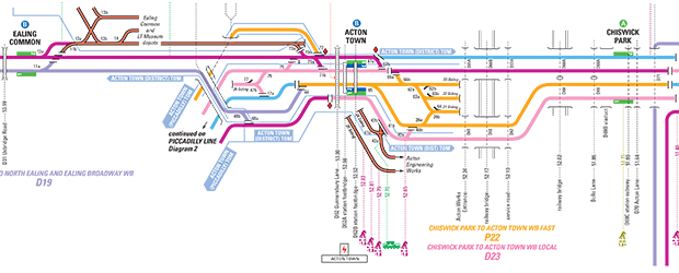
We undertook a major programme of work for London Underground, which resulted in the production of 24 large format diagrams covering all ten of its operational Lines. These include details of: power supply sections, sub-stations, station and track management divisions, asset codes, platform configurations and types, tunnel types, ventilation, engineering access points and capacities (there are thousands), bridge types with inventory codes, track measurements and so on. Each diagram was compiled by FWT from over 20 disparate sources and many site surveys. We also collated the diagrams and supplied them, ready for use, in heavy duty loose-leaf D-ring binders, which we designed ourselves and had made for less than half the cost of standard quality proprietary ones.
As well as a highly versatile portable paper product this suite of diagrams is now also in use on London Underground’s intranet site. We then created the whole set, with other supporting data, as an interactive memory stick for ultimate portability.
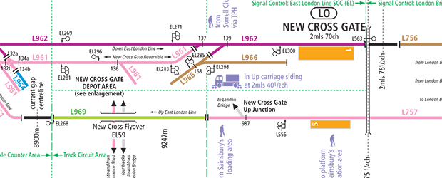
Having seen these, London Overground approached us to produce a single diagram 4.5 metres long, to aid as a planning tool for their track, signalling and platform upgrade programme. This was a most interesting challenge as the diagram needed to depict the entire railway as a straight line, but to scale, taking into account conflicting imperial and metric track measuring systems. This was not a job for the faint hearted.